Defining 2D zones and 2D boundaries
Define 2D zones and 2D boundaries in preparation for creating a 2D mesh.
Tutorial resources
These downloadable resources will be used to complete this tutorial:
Step-by-step guide
To generate a 2D mesh, the 2D zone and 2D boundaries must be defined.
2D Boundary: Primarily defined by boundary edge of 2D zone.
2D Boundary Objects:
- Porous wall, porous polygon, base linear structure, or 2D boundary co-linear with boundary of 2D zone.
- Define alternative boundary conditions for flow to exit under, or to bring flow into, the 2D zone.
- Conditions override 2D zone boundary type where boundary line and polygon boundary coincide.
- Must be fully co-linear with boundary of 2D zone to pass validation.
2D Zone Boundary:
- All 2D zone boundary types are available for 2D boundaries.
- Can assign boundary type of Inflow, Level, or Level & head/discharge to a 2D boundary.
- For Vertical wall, boundary line is considered impermeable infinitely high barrier.
- For porous wall, porous polygon, or base linear structure, coincident portions of wall/polygon are considered infinitely high, regardless of specified crest level.
- For Dry condition, boundary line considered bordered by bottomless pit.
- For Normal Depth condition, assumed that slope balances friction forces (normal flow).
- Depth and velocity kept constant when water reaches boundary, so water flows out without energy losses.

To define a 2D boundary:
- From the File menu, select Open > Open transportable database.
- Navigate to the folder where the exercise files for this tutorial are located.
- Select Def_2d_Zns_Bndr.icmt.
- Click Open.
- If a popup appears regarding opening the database as read-only, click Yes.
- In the Explorer window, right-click the top-level folder and select Copy.
- Right-click the Database and select Paste.
- In the Copying popup, enable Copy ground models.
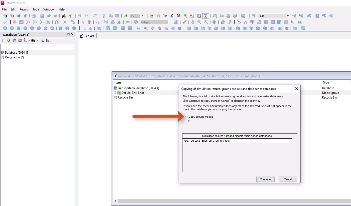
- Click Continue.
- In the Database, right-click the new model group and select New InfoWorks > InfoWorks Network.
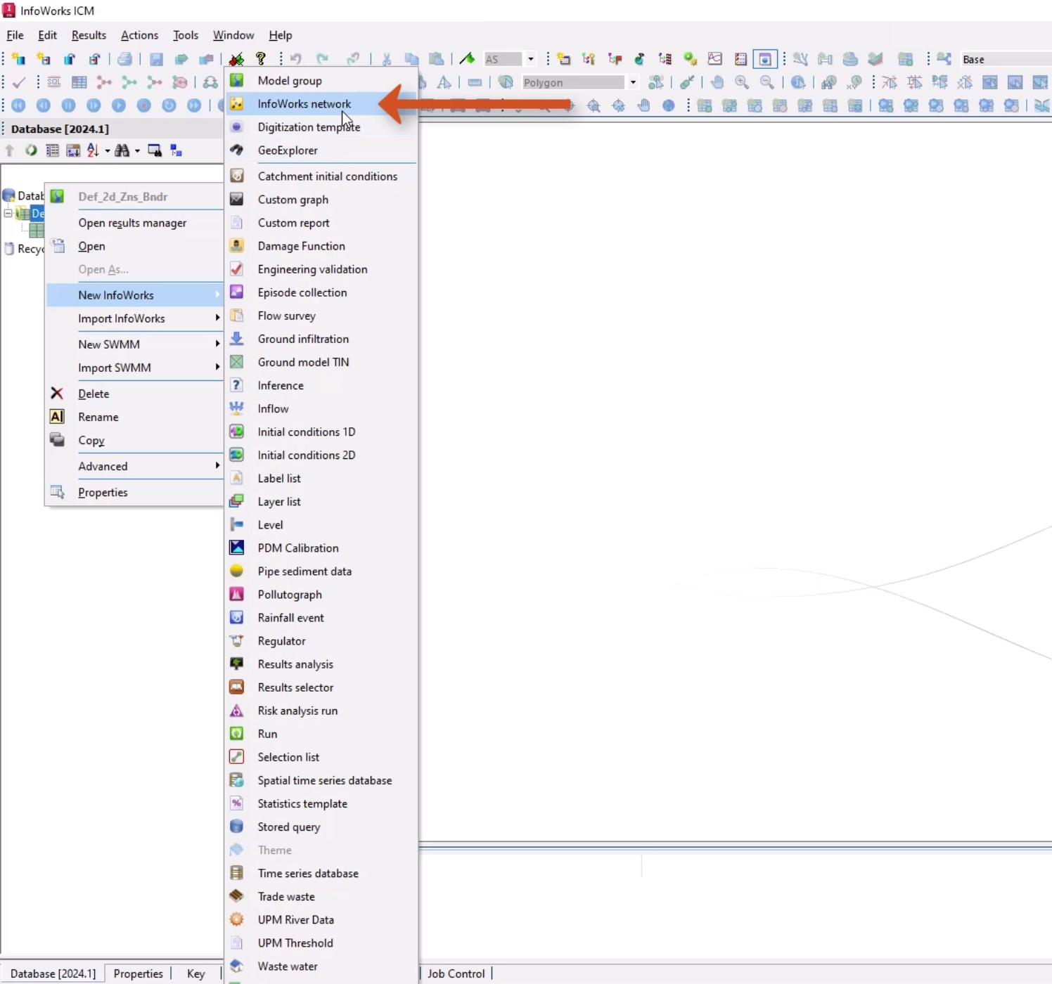
- Add a name of “2D River Model”.
- Click OK.
- Double-click 2D River Model to open the blank network on the GeoPlan.
- Drag the 2D Ground Model and drop it onto the open network.
- Right-click the GeoPlan and select Zoom to ground model.
The bed level is in the center with very steep sides. This tutorial simulates flow travelling from the bottom left to the top right.
To define the 2D zone for mesh generation:
- From the GeoPlan Tools toolbar, expand the New Object Type drop-down and select Polygon.
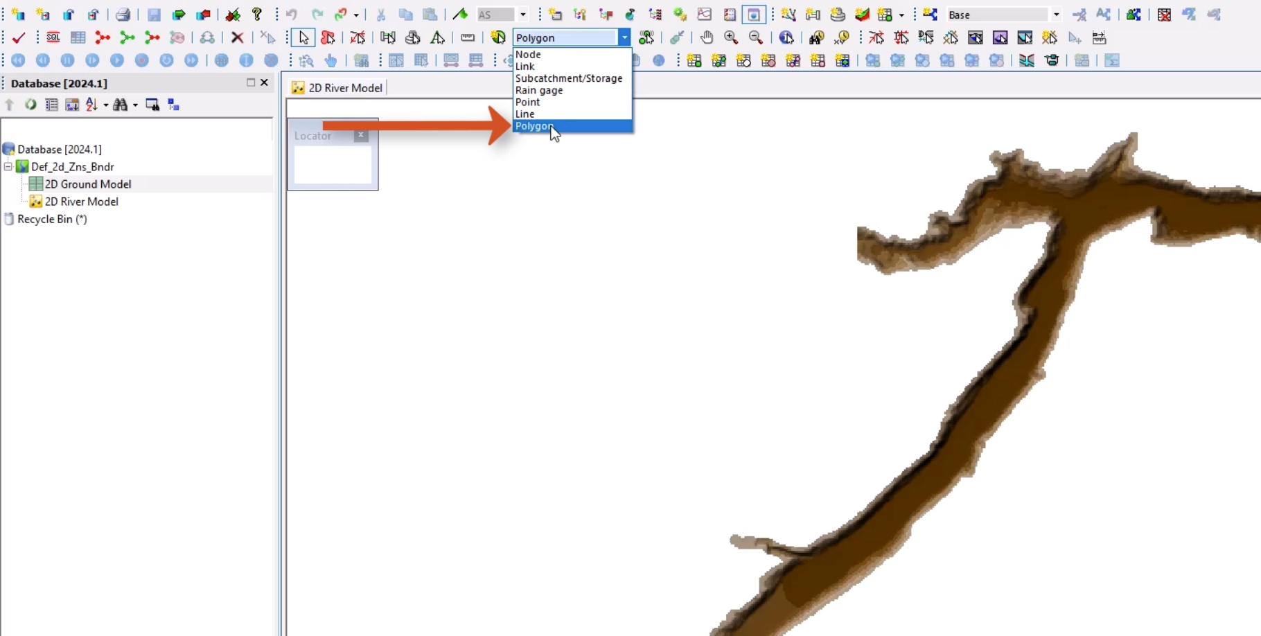
- Digitize a 2D zone polygon within the confines of the ground model by plotting vertices along its edge.
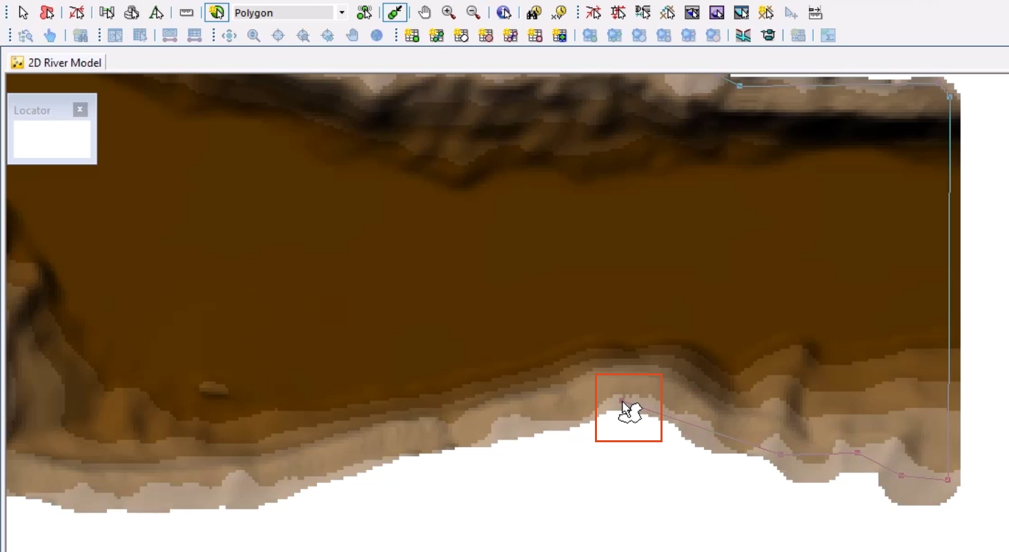
Ensure that all of the polygon is within the ground model, or an error will be generated during meshing.
- Double-click to close the polygon.
- In the New Polygon popup, set both the ID and Type to 2D Zone.
- Click OK.
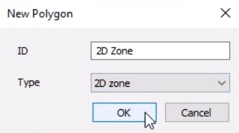
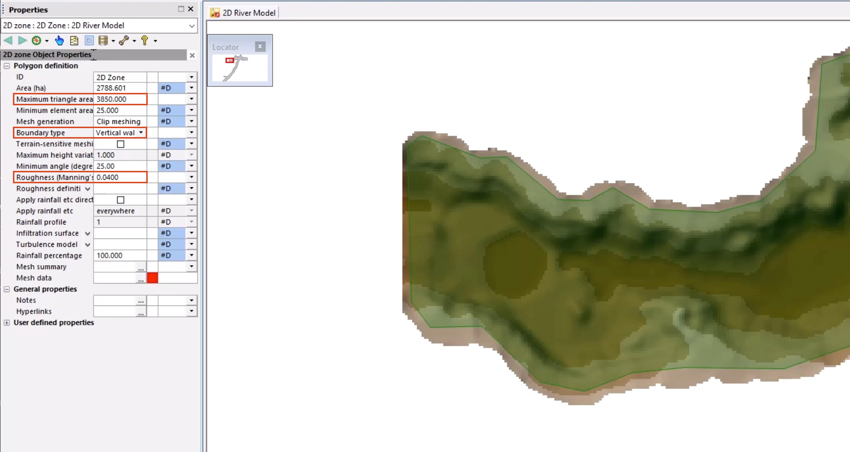
- In the 2D Zone Properties window, change the Maximum Triangle Area to 3850 m2.
- Set the Roughness (Manning’s n) to 0.04.
This provides the parameters for the 2D Zone from which the 2D mesh is created.
To define how flow is allowed out of the 2D zone:
- Set the Boundary Type to Vertical Wall. Any water reaching the edge will act as if it is hitting an infinite wall.
Note that the inline validation error in the Mesh data field will be rectified once the mesh is generated.
Next, define an alternative boundary—in this case, a 2D boundary line—to assign an inflow point:
- In the lower left corner of the model network, zoom in on the upstream end of the 2D zone.
- From the GeoPlan Tools toolbar, expand the New Object Type drop-down and select Line.
- Click New Object.
Digitize a 2D boundary line from left to right, making sure that the line shares the 2D zone vertices of the 2D zone polygon. The ALT or CTRL keys can be used to auto-trace and snap to vertices on the 2D zone between the vertices.
- Click the starting point on the 2D zone boundary.
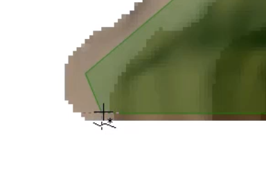
- Press and hold the CTRL key and click on the end point.
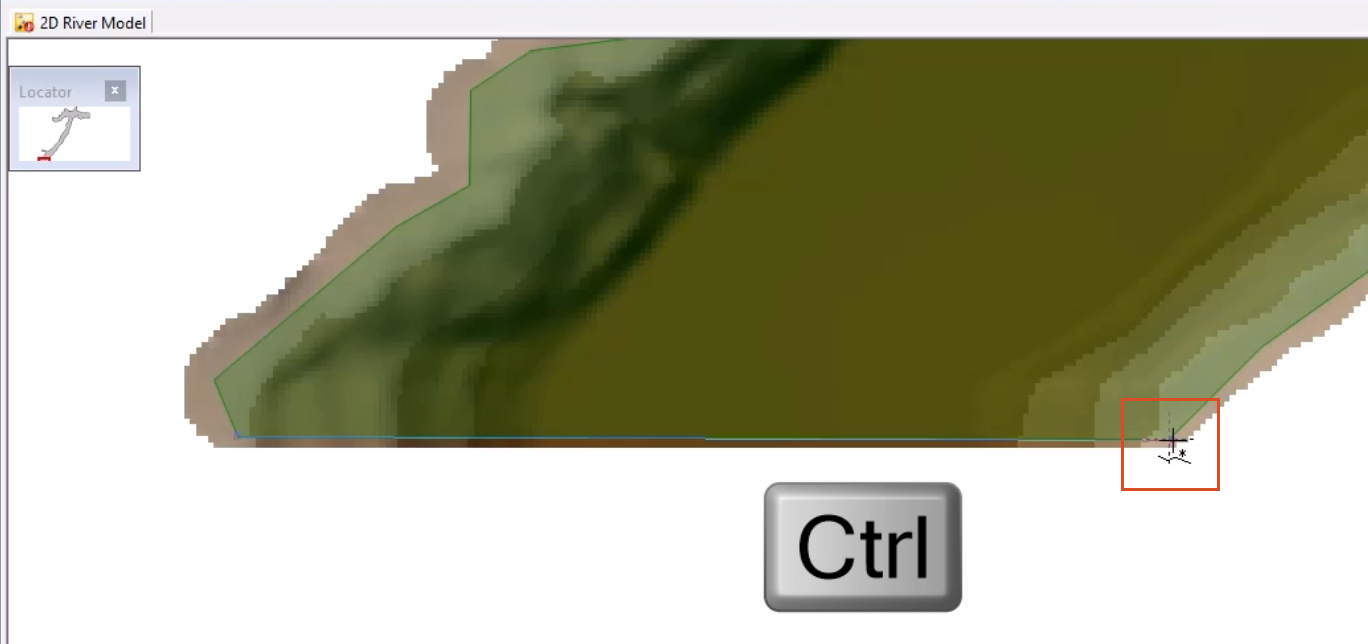
- Add a name of “2D Boundary”, ensuring that the name matches that of the inflow object ID within the Inflow event object.
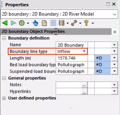
- In the Properties window, set the Boundary line type to Inflow.
Now that the 2D boundaries are defined, the next step is to generate a 2D mesh.