Working with drawings in AutoCAD LT
Learn how to start a new drawing or modify an existing one.
Drawing template files
A drawing template file allows you to specify and save settings for text, dimensions, linetypes, and several other features.
Click New to choose from several drawing template files:

Using and creating your own drawing template files will help save time and improve your workflow.
- Use acadlt.dwt for imperial (inches) and acadltiso.dwt for metric (millimeters).
- You can save any drawing (.dwg) file as a drawing template (.dwt) file.
- To modify an existing drawing template file, click Open, specify Drawing Template (*.dwt) in the Select File dialog box, and choose the template file.
Units

When you start a new drawing, decide what the length of one unit represents—an inch, a foot, a centimeter, a kilometer, or some other unit of length.
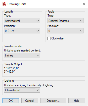
The UNITS command lets you control several unit display settings, including format (or type) and precision.
If you plan to work in feet and inches, use the UNITS command to set the unit type to Architectural, which displays the appropriate symbols when you specify object length in inches. If you plan to use metric units, leave the unit type set to Decimal.
Tip: Create your drawings at full size (1:1 scale). Later, when you create the layout, you'll specify the scale for printing a drawing on a standard-sized specified sheet.
User coordinate system
The UCS, or user coordinate system icon, shows you the direction of the Cartesian coordinate system axes.
The UCS defines:
- Horizontal and vertical directions used for features like Ortho mode, polar tracking, and object snap tracking.
- Alignment and angle of the grid, hatch patterns, text, and dimension objects.
- Origin and orientation for coordinate entry and absolute reference angles.
By default, the UCS icon appears in the lower left corner of the drawing window. Watch this video to understand more UCS basics.